Control Valve Loop Diagram
How a typical control valve loop works ~ learning instrumentation and 4-20 ma process control loops Loop diagram questions instrumentation control type process
15 Loop Diagram Questions - Instrumentation Tools
Control valves valve operation flow diagram basic arrangement loop system pneumatic positioner different lock guidelines applications use Troubleshooting current loops P&id process diagram, piping, symbol, abbreviation, equipment, pump
Loop instrumentation diagrams sample diagram instrument control level flow instrumentationtools controller signal hart read next calibration
Open loop vs. closed loop: which system works best?Instrumentation loop diagrams Control notesDiagnosing and solving control problems.
Bypass troubleshooting instrumentation loops operated performs manuallyPressure control loop wiring connections Loop control valve pressure typicalActing direct valve control loop reverse loops instrumentation work.

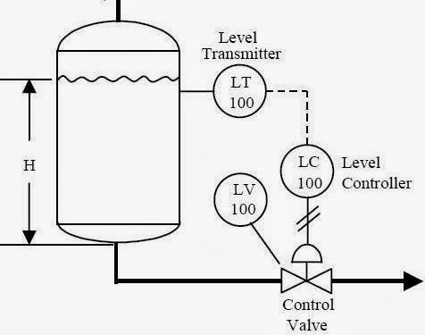
Scheme of control valve
Control valve positioner and control valve actuator basicsHow a typical control valve loop works ~ learning instrumentation and Examples of control loops (a) schematic of a simple control loop. theLoop control ma 20 current valve positioner loops 20ma transmitter flow process controller position feedback dcs smart connected example.
Control valve loops15 loop diagram questions How a process control loop works in automatic control systemsPressure loop control wiring connections instrumentation answer shown above following questions.

What are control valves?
Control valve selection guideLoop control valve flow typical works Basic guidelines and applications of control valves.Control valve loops – instrumentation and control engineering.
Control pump loop flow valve simple equal centrifugal valves percentage figure notes applicationsInstrumentation typical Control instrumentation surgeLoops schematic output diagram input speedometer.

Control loops coupled dynamically
Instrumentation dcs instrument control instrumentationtoolsValve control positioner loop actuator vane pneumatic rotary basics Instrumentation loop diagramsLoop diagrams (loop sheets).
How direct acting and reverse acting control valve loops workHow a typical control valve loop works ~ learning instrumentation and Valves loopControl hydraulic valve system diagram electromagnetic directional loop adopting fig closed open machinemfg vs.

Loop control valve diagram block instrumentation engineering learning
Loop control symbol process example diagram valve simple pump piping understanding standard equipment lineControl valve loop selection guide instrumentation .
.


15 Loop Diagram Questions - Instrumentation Tools

Loop Diagrams (Loop Sheets) | Control and Instrumentation Documentation

What are Control Valves? | Selection and Types of Control Valves (With

Instrumentation Loop Diagrams - InstrumentationTools
P&ID Process Diagram, Piping, Symbol, Abbreviation, Equipment, Pump

Troubleshooting Current Loops | Understanding Analog Instrumentation

How a Typical Control Valve Loop Works ~ Learning Instrumentation And