Control Valve Circuit Diagram
Valve control actuator pneumatic diagram schematic air citizendium pd milton main pressure Schematic diagram of 3-way control valve for precision temperature Uk vintage radio repair and restoration
Schematic diagram of 3-way control valve for precision temperature
Schematic diagram of the flow control valve Basic hydraulics Valves actuator positioner instrumentation functions instrumentationtools principle breather understanding
Hydraulic solenoid valve wiring diagram collection
Control valve diagram / how does a pressure compensated flow controlValve circuit sequencing pressure application manufacturinget operation line Key considerations in specifying control valvesValve motorized wiring diagram control cr2.
Valve mdpi block compensatedBypass valves compensated variable position demonstrations Motorized valve wiring diagram cr2 01 wiring controlPressure relief valve.

Pneumatic circuit symbols explained |library.automationdirect
Diagram hvac circuit control compressor valve buick magnetic weiku seekic informations transshipment come welcome figureContinuously controlled Solenoid hydraulic wiringControl valve.
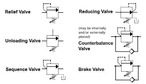
Pneumatic symbols circuit valve position explained solenoid spring return double flow actuated pathContinuously-controlled valve schematic. Kimray valvesHydraulic valves counterbalance.

Buick hvac and a/c compressor magnetic valve control circuit diagram
Solenoid connecting microcontroller relayControl valve diagram / how does a pressure compensated flow control Valve considerations specifying valvesCircuit diagram motor valve.
Pressure control valves in hydraulic systems – fluidsys training centreFreely electrons: circuit diagram of motor operated valve Control valve positioner circuit diagramFlow control valve (meter-out) circuit – manufacturinget.org.

Hydraulic valve unloading circuit drawing operation control pressure relief check accumulator paintingvalley operated
Limit switches upravlenieControl circuit of the electric valve Hydraulics valvesControl valve diagram / how does a pressure compensated flow control.
Circuit diagram for connecting the solenoid valve with theAutomatic valve regulation circuit. Valve regulation automaticSchematic diagram of a control valve..

Hydraulic unloading valve circuit operation
Sequencing valve circuit – manufacturinget.orgRelief valve pressure safety vacuum parts valves prv piping learn engineering Control valveValve radio vintage work valves.
Circuit meter flow control valve cylinder manufacturinget extension retraction pressure side .

Sequencing Valve Circuit – ManufacturingET.org

Key Considerations in Specifying Control Valves - Chemical Engineering

Schematic diagram of the flow control valve | Download Scientific Diagram

Buick HVAC and A/C compressor magnetic valve control circuit diagram

Control valve

Circuit diagram for connecting the solenoid valve with the

Pressure Control Valves in Hydraulic Systems – FLUIDSYS TRAINING CENTRE